Leave Your Message

How to Choose the Right PMSM Motor for Your Application

Choosing the right Pmsm Motor starts with the work it must perform, not with a catalog headline. A compact robot joint needs different torque and speed characteristics from a pump running steadily through a long shift. Small details matter: a brief startup surge, frequent reversals, limited airflow, or a hot enclosure can change the motor requirement. There is no universal “best” choice.

A useful selection begins with the application’s operating profile. Record continuous and peak torque, speed range, acceleration time, duty cycle, supply voltage, and available mounting space. Then compare motor curves and thermal limits, rather than relying on rated power alone. The controller matters, too; confirm its voltage, current, feedback, and control method work with the motor. Check the shaft, bearings, and cooling arrangement against the real installation. Dust, vibration, and ambient temperature are easy to overlook. They should not be.

Efficiency is important, but it is only one part of the decision. A smaller motor may reduce cost and space, yet leave little margin for overloads or heat. A larger unit can add expense and affect system response. Review the manufacturer’s data, ask how ratings were measured, and validate the choice under realistic load conditions when possible. A prototype test may reveal a mismatch that a spreadsheet misses. Even careful calculations depend on assumptions, and those assumptions deserve another look. This guide outlines the key trade-offs so you can make a defensible choice for your application.
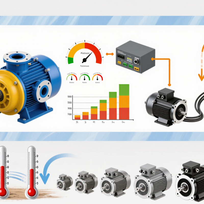
How to Choose the Right PMSM Motor for Your Application

Define the Application Requirements and Performance Goals

A suitable PMSM starts with a clear picture of the application, not a motor catalog. Record the required speed range, continuous torque, peak torque, and operating time. A conveyor moving cartons steadily has different needs from a robotic joint that accelerates and stops repeatedly. Start with measurements. Estimate the load’s inertia and note how often it starts, reverses, or runs at full speed. These details shape motor size and thermal demands.

Turn broad goals into measurable limits. Specify the available DC bus voltage, controller current, installation space, ambient temperature, and acceptable noise. Define acceleration time and speed stability too. Peak matters too. A motor may deliver high torque briefly but overheat if that demand repeats too often. Compare continuous ratings under realistic cooling and mounting conditions, not just ideal test conditions. If load data is uncertain, measure it or state the assumption; a neat spreadsheet can still hide a poor estimate.

Tips: Write down normal and worst-case operating cycles before choosing. Include a little margin, but avoid oversizing without reason, since it can add cost and reduce efficiency. Then check the candidate against the actual duty cycle. Leave room for uncertainty. A prototype test may reveal vibration or heat that calculations missed.
Assess Load Characteristics and Operating Conditions

A PMSM selection starts with the load, not the nameplate. Record required torque and speed across the full operating cycle, including startup, acceleration, and brief overloads. A conveyor carrying wet material may need high breakaway torque; a fan usually needs less torque at low speed. These differences shape motor sizing, control strategy, and thermal limits. The IEA’s 2011 report on electric motor-driven systems estimates they use about 45% of global electricity. Small efficiency gains matter, but only when the motor suits its actual load.

Next, check the real operating environment. Note ambient temperature, dust, moisture, vibration, available cooling, and how often the motor starts and stops. Match these conditions to the enclosure, insulation, and duty rating. The U.S. Department of Energy’s 2014 motor-systems sourcebook reports that motor-driven systems use about 68% of U.S. manufacturing electricity. That figure describes a broad industrial category, not one machine, but it underlines the value of measuring operating hours and load variation.

A variable-speed pump may spend much of its life below rated speed, while a press may face short, sharp torque peaks. Use measured current, speed, and process data where possible; estimates can miss the worst moments. Leave a sensible thermal margin, but avoid oversizing by habit. It is easy to overlook heat buildup during repeated starts. Check the duty cycle again. Real loads are rarely tidy.

Select PMSM Motor Type, Size, and Key Ratings

Choosing the right PMSM begins with the load’s torque-speed curve, not the motor’s advertised peak power. Surface-mounted designs suit many steady-speed duties; interior-magnet designs can provide useful reluctance torque and a wider constant-power range. Check the full operating envelope. A conveyor, for example, needs strong starting torque, while a spindle may spend more time at high speed.

Size the motor for continuous torque at the actual duty cycle, then verify short-duration peak torque, acceleration, and overload time. IEA’s Global EV Outlook 2024 reports nearly 14 million electric cars were sold in 2023, about 18% of global car sales. That growth highlights why compact traction motors matter, but vehicle figures cannot size an industrial drive. Match rated voltage and speed to the inverter, and confirm cooling, insulation, encoder, and ingress-protection needs.

Leave thermal margin. A motor that meets a peak number may still overheat during repeated starts or low-speed operation. Check the rating conditions: ambient temperature, mounting, cooling method, and duty class can change usable output. There is no perfect pick. A first sizing pass is rarely final; validate it against measured load data, and revisit assumptions when the machine behaves differently.

Match the Motor with a Suitable Drive and Control System

How to Choose the Right PMSM Motor for Your Application

A PMSM can deliver precise torque and smooth motion, but its drive must suit the motor’s electrical limits. Check the rated voltage, continuous current, and peak current against the drive specifications. A voltage mismatch can reduce available speed, while undersized current capacity may cause trips during acceleration. Small details matter.

Match the control method to the application. Field-oriented control is commonly used for responsive torque and stable operation across a broad speed range. Confirm that the drive supports the required feedback device, such as an encoder or resolver, and that its input matches the sensor’s signal type. Sensorless control may simplify wiring, but low-speed performance can vary with the motor and load.

Think about the machine, not just the motor. A conveyor with steady loads has different demands from a spindle that accelerates quickly. For frequent starts and stops, check peak torque duration, braking needs, and thermal limits. During commissioning, tune the control loop gradually and watch current, temperature, and vibration. A low-speed test can reveal rough motion that a high-speed run hides. A tidy spreadsheet may still miss cable length, mounting resonance, or a changing load; leave room for testing under real operating conditions.

Verify Integration, Efficiency, and Application Compatibility

Start with the interface, not the nameplate. Record bus voltage, peak and continuous torque, speed range, shaft dimensions, mounting pattern, feedback type, and cooling limits. Confirm the inverter supports the motor’s electrical characteristics, commutation method, and encoder signals. A mismatch can cause nuisance trips, poor low-speed control, or excess heat. Leave room for wiring bends and service access; drawings can hide these constraints. Fit matters.

Efficiency must match the real duty cycle, not just a headline peak. Map starts, dwell periods, load changes, ambient temperature, and regenerative braking before comparing candidates. The IEA’s 2011 report, Energy-Efficiency Policy Opportunities for Electric Motor-Driven Systems, estimates motor systems use about 45% of global electricity. The U.S. Department of Energy’s 2008 Motor Systems Sourcebook reports that motor-driven systems account for roughly 70% of industrial electricity use. Small integration losses deserve attention. Compare motor-and-drive efficiency across operating points, then verify temperature rise inside the actual enclosure. An open-bench test may not represent a sealed machine. I would revisit the assumptions after the first prototype; calculated thermal margins can be optimistic.

How to Choose the Right PMSM Motor for Your Application

Compare the calculated shaft torque at three example operating points. These are illustrative design points, not universal application requirements.

Torque is calculated from rated mechanical power and speed using T (N·m) = 9550 × P (kW) ÷ n (rpm). Before selecting a motor, confirm its torque-speed curve covers the full duty cycle, then check inverter and supply compatibility, mounting and shaft dimensions, feedback requirements, cooling, and efficiency at the expected operating points.