Choosing the right Worm Motor is not a catalog exercise. It is a practical engineering decision involving torque, speed, duty cycle, load behavior, and operating conditions. A motor that performs well on a test bench may overheat beside a dusty conveyor or fail under repeated shock loads.
The International Energy Agency reports that motor-driven systems consume nearly half of global electricity. The U.S. Department of Energy also identifies motor systems as a major source of industrial energy use. These findings make correct motor selection important for both reliability and operating cost. Recent market studies from Grand View Research and MarketsandMarkets link worm-gear demand with automation, material handling, packaging, and compact power transmission. However, market forecasts use different definitions. Their figures should guide discussion, not replace engineering calculations.
In practical selection work, engineers usually begin with the driven machine, not the motor nameplate. Required output torque, starting torque, ratio, cycle frequency, and mounting position must be verified. Ambient temperature matters. So does lubrication. A small gearbox running continuously at 60°C needs different protection from one operating intermittently in a clean indoor line. Worm drives can offer quiet operation and high reduction ratios, but their sliding contact may reduce efficiency and increase heat. That trade-off is easy to overlook. It deserves careful review.
This guide explains how to compare Worm Motor options using measurable application data. It also considers service factor, efficiency class, braking needs, ingress protection, and maintenance access. No single rating fits every machine. A cautious decision may prevent an expensive redesign.
How to Choose the Right Worm Motor for Your Application?
Understanding Worm Motor Design and Operating Principles
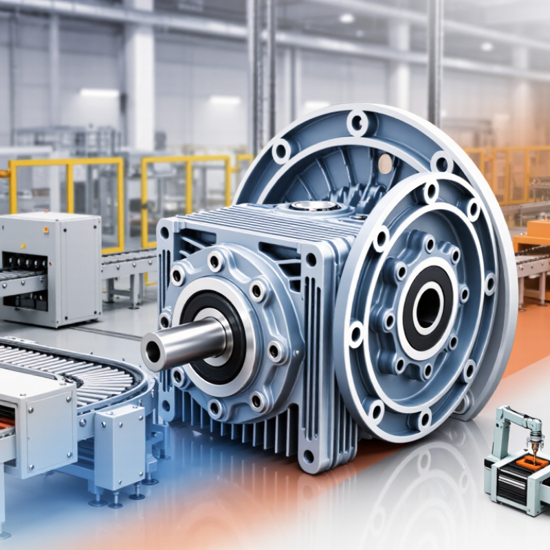
A worm motor combines an electric motor with a worm gear reducer. The motor turns a hardened steel screw, called the worm. This screw drives a toothed wheel at a right angle. Their contact creates high reduction in a compact housing. It also produces useful output torque at low speed. The ratio depends on the worm’s lead and the wheel’s tooth count. Small changes matter.
Efficiency is often lower than other gear systems because sliding friction generates heat. Check the rated torque, speed, duty cycle, and operating temperature together. A motor may meet the torque requirement but still overheat during repeated starts. In practical testing, measure the housing temperature after a realistic workload. It should not feel dangerously hot. That simple check can reveal an undersized design.
Self-locking behavior needs careful judgment. Some worm motors resist backdriving, but this is not guaranteed under every load or angle. Vibration, lubrication, wear, and gear geometry can change the result. Never treat self-locking as the only safety control. Select suitable bearings, seals, and lubricant for dust, moisture, and installation position. Voltage compatibility matters too. I would also question oversized motors, since they can waste energy and increase starting stress. A quieter, cooler motor with adequate reserve is usually the more dependable choice.
Worm motor selection begins with the required output speed and torque. This chart shows the theoretical output speed produced by common worm gear ratios when using a 1,750 rpm motor. A higher ratio provides lower speed and greater torque multiplication, while generally requiring more attention to efficiency and heat dissipation.
Output speed is calculated as motor speed ÷ gear ratio. Actual operating speed may be slightly lower because of load, slip, and mechanical losses. The final motor should also be checked against starting torque, duty cycle, thermal limits, mounting orientation, and required service factor.
Choosing a worm motor begins with the load, not the catalog speed. In field sizing, I record running torque, breakaway torque, duty cycle, and shaft orientation. The basic relation is T = 9550P/n, using newton-metres, kilowatts, and revolutions per minute. A conveyor needing 120 N·m at 30 rpm requires about 0.38 kW before losses. That figure is only a starting point.
Worm gearing can lose substantial power through sliding contact. Technical studies commonly report efficiencies from 50% to 90%, depending on ratio, lubrication, speed, and load. The U.S. Department of Energy’s Motor Systems Market Assessment identifies motor-driven equipment as roughly 70% of industrial electricity use. Efficiency matters, even on small machines. Select capacity above calculated demand, but avoid excessive oversizing. It may increase heat, cost, and poor low-load performance. Check thermal ratings for continuous duty, starts per hour, ambient temperature, and enclosure protection.
Speed matching means more than dividing motor rpm by ratio. Confirm output speed under load, not only no-load speed. Check radial and axial shaft loads, backlash, braking needs, and claimed self-locking behavior. It often is not guaranteed. IEC 60034-1 supports motor rating checks, while ISO 14521 addresses worm gear load-capacity calculations. I have seen units pass torque calculations but fail startup testing. That mistake is expensive. Measure startup current and temperature during a representative trial, then reconsider the selection.
| Application Example | Typical Load Characteristic | Required Output Speed | Typical Output Torque | Suggested Reduction Ratio | Typical Motor Power | Recommended Service Factor | Key Selection Considerations |
|---|---|---|---|---|---|---|---|
| Small conveyor | Continuous movement with moderate starting load | 20–60 rpm | 10–40 N·m | 20:1–60:1 | 0.12–0.37 kW | 1.25–1.50 | Check belt tension, starting torque, duty cycle, and allowable radial load on the output shaft. |
| Packaging or indexing equipment | Intermittent operation with frequent starts and stops | 10–40 rpm | 15–60 N·m | 30:1–80:1 | 0.25–0.75 kW | 1.50–2.00 | Allow for acceleration torque, stopping frequency, thermal cycling, and possible use of a brake. |
| Mixer or agitator | High breakaway torque and variable process resistance | 10–50 rpm | 40–150 N·m | 30:1–100:1 | 0.55–2.20 kW | 1.75–2.50 | Use a higher service factor where the material can settle, thicken, or create sudden resistance during startup. |
| Valve or damper actuator | Short-duration positioning with high static holding demand | 1–15 rpm | 30–200 N·m | 60:1–300:1 | 0.09–0.55 kW | 1.25–1.75 | Confirm required travel time, holding torque, number of cycles per hour, and whether a mechanical brake is necessary. |
| Lift table or compact hoist | High starting load with potential suspended-load hazard | 5–30 rpm | 50–250 N·m | 40:1–150:1 | 0.37–2.20 kW | 2.00–3.00 | Do not rely on worm self-locking alone for personnel or safety-critical lifting. Provide an independently rated brake and load-retention system. |
| Rotary gate or positioning mechanism | Low-speed motion with occasional high static load | 2–20 rpm | 25–180 N·m | 60:1–250:1 | 0.12–1.10 kW | 1.50–2.00 | Evaluate backlash, angular positioning accuracy, duty cycle, and the torque required to overcome seal friction. |
| Turntable or display platform | Low-speed continuous or intermittent rotation | 1–10 rpm | 8–80 N·m | 80:1–300:1 | 0.06–0.37 kW | 1.25–1.50 | Check platform inertia, eccentric loading, smoothness requirements, noise limits, and permitted output-shaft overhung load. |
| Small fan or air-handling damper | Light to moderate load with relatively smooth operation | 20–100 rpm | 5–30 N·m | 10:1–50:1 | 0.09–0.55 kW | 1.15–1.35 | Confirm continuous-duty thermal capacity, ventilation, ambient temperature, and required airflow control range. |
| Agricultural feed or grain conveyor | Continuous load with dust, contamination, and occasional blockage | 15–50 rpm | 25–120 N·m | 30:1–100:1 | 0.37–1.50 kW | 1.75–2.50 | Use suitable enclosure protection, verify sealing requirements, and size for jam-clearing torque without exceeding gearbox limits. |
| Light-duty positioning slide | Short travel, low inertia, and controlled intermittent movement | 5–40 rpm | 5–35 N·m | 30:1–120:1 | 0.06–0.37 kW | 1.25–1.75 | Prioritize low backlash, repeatability, acceleration control, and compatibility with the selected controller or variable-frequency drive. |
Torque is the starting point when selecting a worm motor. Estimate the load, lever arm, acceleration, and starting resistance. A conveyor moving heavy material may need far more starting torque than running torque. Include a service margin, but avoid oversized motors that waste energy and space. Then check the motor’s rated output torque at the required speed.
Gear ratio controls the balance between speed and torque. A higher ratio usually delivers more output torque and slower movement. It can also increase friction and reduce efficiency. Worm motors often operate below the efficiency of many other gear systems, especially at high reduction ratios. Measure performance under real conditions, not only from catalog data. Lubricant temperature, shaft alignment, duty cycle, and load direction can change the result. Small details matter.
During commissioning, I record input current, output speed, surface temperature, and operating noise. These readings reveal problems that calculations may miss. A motor that feels powerful during a brief test may overheat during continuous operation. Do not assume that every worm gearbox will self-lock safely; vibration, wear, and load conditions can affect holding ability. Every application is different. A spreadsheet helps, but it can mislead. Recheck the choice after testing the motor with the actual load, especially when efficiency, heat, or precise positioning matters.
Choosing a worm motor starts with the working environment, not the catalog rating. Steel housings suit general industrial areas, while aluminum reduces weight and resists surface corrosion. Stainless steel helps in damp, washdown, or chemically exposed locations. The worm and wheel materials also matter. Hardened steel worms paired with bronze wheels can reduce wear and heat during repeated operation. Plastic components may suit light loads, but they need careful temperature and torque checks.
Mounting affects alignment, cooling, and service life. Foot-mounted motors work well on rigid frames and conveyors. Flange-mounted designs save space near gearboxes or machinery panels. Confirm the shaft direction, bolt pattern, and available clearance before ordering.
Fit matters. A small misalignment can create noise, vibration, and premature bearing damage.
Include access for lubrication, cable routing, and inspection. In practice, installers often focus on torque and overlook maintenance space.
Protection ratings should match real exposure, not an imagined worst case. An IP rating indicates resistance to solids and water, but it does not define chemical compatibility or impact strength. For dusty indoor areas, sealed construction may be adequate. Outdoor or washdown applications usually need stronger protection and suitable cable glands. Higher protection is not automatically better; it can increase cost and limit heat release.
Check ambient temperature, duty cycle, condensation, and cleaning methods together.
Do not guess.
A conservative selection is useful, but excessive caution can create an unnecessarily heavy and inefficient motor.
Choosing a worm motor starts with real application conditions, not a catalog rating. Record the required load, output speed, duty cycle, mounting position, and starting frequency. Consider shock loads, ambient temperature, humidity, dust, and available space. A motor that performs well during a short test may overheat during continuous operation. Check starts carefully. Self-locking is not guaranteed under every load or vibration condition. Efficiency also changes with speed, lubrication, and gear ratio.
Maintenance should be planned before installation. Inspect lubricant levels, seals, fasteners, and unusual noise at regular intervals. Worm drives create sliding friction, so incorrect lubricant can raise temperature quickly. Keep cooling surfaces clean, especially in dusty workshops. A simple maintenance log can reveal rising noise or current draw before failure occurs. Service intervals should follow tested operating conditions, not guesswork. This is where selection decisions often become imperfect.
Total cost includes energy use, replacement parts, labor, downtime, and disposal. A lower purchase price may become expensive when efficiency is poor or service access is difficult. Estimate annual operating hours and compare energy consumption at the actual load, not the maximum rating. Request documented data for efficiency, thermal limits, permissible loads, and service factors. A careful supplier should explain test conditions clearly. Real installations rarely match ideal calculations, so allow a practical safety margin without oversizing the motor unnecessarily.