Leave Your Message
Why Choose a Gear Motor for Industrial Applications?
Industrial machinery rarely has room for wasted motion, excess heat, or uncertain torque. A Gear Motor combines an electric motor with a gearbox, creating compact and controlled power transmission. This arrangement can drive conveyors, mixers, packaging lines, pumps, and automated doors with dependable speed reduction. In a factory, that difference is visible. A conveyor starts smoothly, carries a heavy crate, and maintains its pace without demanding a large external transmission system.
Mechanical reliability expert Heinz P. Bloch has often emphasized, “Reliability is a function of design.” His observation applies directly to Gear Motor selection. Engineers must match rated torque, service factor, output speed, duty cycle, and environmental protection. A unit operating beside a washdown line needs suitable sealing and corrosion resistance. One installed near a furnace may require better thermal management. Small details matter. Poor sizing creates noise, overheating, and premature bearing wear. Bigger is not always better.
The practical advantage is efficiency through integration. Fewer exposed components can simplify installation, alignment, and routine inspection. Helical, worm, planetary, and bevel gearboxes each offer different benefits. Worm designs may provide high reduction in limited space, while helical units often deliver stronger efficiency. Yet no design is perfect. Lubricant condition, mounting position, shock loads, and maintenance habits still influence service life. This is where experience challenges simple specifications. A Gear Motor should be selected from real operating conditions, not catalog numbers alone. The right choice can reduce downtime, but only when engineering judgment continues after purchase.
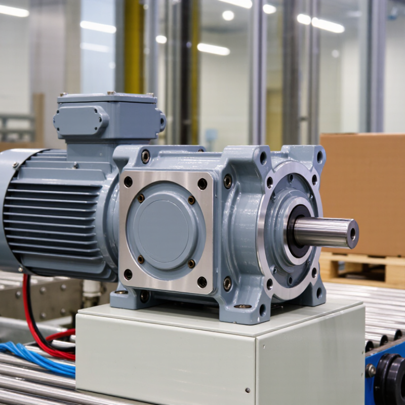
A gear motor combines an electric motor with a gearbox in one compact drive unit. The motor creates rotational force, while the gearbox changes speed and torque. Gear teeth transfer motion through fixed ratios. Lower output speed produces higher usable torque. Simple, but not frictionless.
The International Energy Agency reports that electric motor-driven systems consume roughly 53% of global electricity. The U.S. Department of Energy’s Improving Motor and Drive System Performance sourcebook estimates that motor systems use about 70% of industrial electricity. These figures explain why gear motor selection deserves careful engineering. A helical gearbox usually offers smooth, efficient transmission. A worm gearbox can provide high reduction in limited space, but it may generate more heat. Planetary designs deliver high torque density when equipment space is restricted.
In a conveyor line, the motor may rotate too quickly for direct connection. The gearbox reduces speed and helps the belt move steadily under changing loads. Output torque depends on motor torque, reduction ratio, and gearbox efficiency. Real systems also lose energy through friction, seals, and heat. Not every high-ratio gearbox is the best choice. Field commissioning often reveals overlooked issues, such as poor lubrication, excessive starts, or an underestimated service factor. Noise and vibration can increase when alignment is imperfect. A practical specification should examine duty cycle, ambient temperature, backdriving risk, maintenance access, and required output speed. The calculation may look correct on paper, yet operating conditions can still expose weak assumptions.
| Data Dimension | Spur Gear Motor | Helical Gear Motor | Bevel Gear Motor | Worm Gear Motor | Planetary Gear Motor |
|---|---|---|---|---|---|
| Gear Motor Design and Operating Characteristics | |||||
| Basic operating principle | Parallel cylindrical gears transmit rotation between parallel shafts. | Angled teeth engage gradually, producing smoother and quieter power transmission. | Conical gears redirect torque, commonly through a 90-degree shaft arrangement. | A worm screw drives a worm wheel, usually producing a large speed reduction in a compact housing. | Multiple planetary gears rotate around a central sun gear to distribute load through several contact points. |
| Common reduction ratio range | Approximately 3:1 to 20:1 per stage; higher ratios may use multiple stages. | Approximately 3:1 to 20:1 per stage; multi-stage designs provide higher reductions. | Approximately 3:1 to 30:1 in common industrial configurations. | Approximately 5:1 to 100:1, depending on design and operating requirements. | Approximately 3:1 to 100:1, with multi-stage versions providing higher ratios. |
| Typical mechanical efficiency | Approximately 70%–95%, depending on the number of stages, lubrication, and load. | Approximately 90%–97% for well-designed single-stage or low-ratio units. | Approximately 90%–96%, depending on ratio, gearing, and bearing losses. | Approximately 50%–90%; efficiency generally decreases as the reduction ratio increases. | Approximately 90%–97% for many industrial configurations, depending on the number of stages. |
| Output speed behavior | Reduces motor speed in direct proportion to the gear ratio. | Provides stable, low-speed output with smooth torque transmission. | Provides reduced speed while changing the direction of power transmission. | Produces very low output speeds and high reduction in a compact arrangement. | Provides precise, stable output speed with low backlash in suitable designs. |
| Noise and vibration level | Moderate; straight-tooth designs can be noisier at higher speeds. | Low to moderate because tooth engagement is gradual. | Moderate; depends on tooth accuracy, alignment, and housing design. | Low to moderate, although sliding contact can generate heat and sound under heavy loads. | Low to moderate, with good balance and load sharing when correctly assembled. |
| Torque density | Low to medium; suitable for general-purpose drive systems. | Medium to high; appropriate for continuous industrial loads. | Medium to high, especially where a right-angle drive is required. | High output torque at low speed, but with greater heat generation at high reductions. | High; multiple gear contacts allow substantial torque in a relatively compact package. |
| Backdriving tendency | Usually backdrivable when external force is applied to the output shaft. | Usually backdrivable unless an additional brake or holding mechanism is used. | Usually backdrivable under many operating conditions. | May resist backdriving at selected ratios, but self-locking should never be assumed without verification. | Generally backdrivable and normally requires a brake for reliable load holding. |
| Maintenance considerations | Requires correct lubrication, alignment, and inspection of gear and bearing wear. | Requires lubricant condition checks, sealing inspection, and alignment control. | Requires attention to lubrication, shaft alignment, and bearing loading. | Requires heat management, lubricant checks, and monitoring for sliding-contact wear. | Requires clean lubricant, accurate assembly, sealing inspection, and backlash monitoring. |
| Typical industrial applications | Conveyors, packaging equipment, feeders, small material-handling systems, and light automation. | Industrial conveyors, mixers, pumps, machine tools, and continuous-duty production equipment. | Right-angle conveyors, hoists, positioning equipment, processing machinery, and material-handling systems. | Gates, lifts, conveyors, rotary tables, actuators, and applications requiring high reduction in limited space. | Robotic axes, indexing systems, servo positioning, printing equipment, and high-precision automation. |
| Why Gear Motors Are Used in Industrial Applications | |||||
| Speed reduction | A gear train reduces the high rotational speed of an electric motor to a more useful output speed for industrial machinery. | ||||
| Torque multiplication | Reducing speed increases available output torque. Actual torque is reduced by mechanical losses, so efficiency must be included in sizing calculations. | ||||
| Compact drive arrangement | The motor and gearbox are integrated into one drive unit, which can reduce installation space, coupling requirements, and alignment work. | ||||
| Controlled motion | Gear motors provide predictable speed and torque for conveyors, mixers, feeders, lifting systems, and automated production equipment. | ||||
| Load-handling capability | The gearbox allows a relatively small motor to handle higher torque demands at lower output speed, provided the gearbox, motor, and duty cycle are correctly sized. | ||||
| Basic Gear Motor Calculation Relationships | |||||
| Output speed | Output speed ≈ Motor speed ÷ Gear ratio. For example, a 1,800 rpm motor with a 30:1 reduction produces approximately 60 rpm before minor operating variations. | ||||
| Output torque | Output torque ≈ Motor torque × Gear ratio × Efficiency. The calculated value must be checked against gearbox ratings, service factor, starting load, and peak torque. | ||||
| Power relationship | Output power = Input power × Efficiency. A gearbox does not create power; it exchanges rotational speed for torque while mechanical losses generate heat. | ||||
| Important selection inputs | Required output speed, continuous and peak torque, duty cycle, starting frequency, shock load, mounting position, ambient temperature, environmental exposure, noise limits, braking needs, and allowable backlash. | ||||