Leave Your Message

7 Tips for Choosing the Right DC DC Motor

Choosing the right Dc Dc Motor begins with the job it must perform, not the largest number on its label. A conveyor moving small packages needs different torque and speed from a compact pump or a precision feeder. Note the load, required speed, duty cycle, and available supply voltage before comparing models. Small details matter: a motor that starts smoothly on a bench may stall when a belt is loaded.

Motor applications engineer Alex Morgan puts it this way: “Choose for the real load, not the ideal test.” That reminder frames these seven tips: match torque and speed, check voltage and current, consider startup demands, account for operating time, assess mounting and shaft dimensions, review the environment, and leave sensible performance margin. Each choice affects the others. Extra torque can mean higher current, more heat, and a larger power supply.

Measure twice. Then compare datasheets. A rated speed alone can mislead; inspect the torque curve and confirm the motor can handle the actual operating point. If the mechanism binds or the load changes, even a well-selected motor may disappoint. That is worth admitting: selection rules cannot replace a test under realistic conditions. A short prototype run, with temperature and current checks, can expose problems before installation. The right Dc Dc Motor is the one that works reliably in your specific system, not merely the one that looks best in a catalog.
7 Tips for Choosing the Right DC DC Motor

Define Load Torque, Speed, and Power Using P = Tω

A motor choice starts with the load, not the motor label. Estimate the torque needed at the shaft under normal operation and during startup. A conveyor carrying boxes, for example, may need a brief torque surge when fully loaded. Record that peak separately from continuous torque. Small details matter.

Mechanical power links torque and angular speed: P = Tω Here, P is power in watts, T is torque in newton-metres, and ω is speed in radians per second. If speed is listed in revolutions per minute, convert it using ω = 2πn/60. For instance, 0.2 N·m at 3,000 rpm requires about 63 W of mechanical output. This is shaft power, not electrical input; motor and drive losses increase the power drawn from the supply.

Check the required torque and speed at the same operating point. A motor’s advertised maximum speed may occur with little or no load, while its peak torque may only be available briefly. That mismatch is easy to overlook. Measure the actual load if possible, using a torque sensor or a safe test setup, then allow sensible margin for friction, temperature, and changing loads. I have seen calculations look neat on paper yet miss startup friction. Treat estimates as estimates, and verify the motor under realistic conditions.

Set Supply Voltage and Current Limits, Including Startup and Stall Current

Set supply voltage and current limits before selecting a DC motor. Check the motor’s rated voltage, continuous current, startup current, and stall current in its datasheet. Startup can briefly draw near-stall current because the rotor has not yet developed back electromotive force. A jam can keep that high current flowing. Heat builds quickly.

Use armature resistance for a rough stall-current estimate: current is approximately supply voltage divided by winding resistance. For example, 12 volts across 0.6 ohms gives an idealized 20 amps. Real measurements vary with temperature, wiring, and brush contact. Treat the calculation as a warning, not a specification. That distinction matters. Size the driver and supply for measured startup peaks, while setting current limiting below levels that could damage the motor or electronics. Do not assume a small motor has a small stall current.

IEEE Std 113-1985 describes test procedures for direct-current machines, including measurements relevant to electrical performance. IEC 60034-1:2022 addresses ratings and performance of rotating electrical machines, but neither provides one universal startup-current multiplier for every DC motor. Record current during a cold start and under the heaviest expected load; repeat tests if the supply voltage or mechanism changes. A current probe helps capture brief peaks that a slow meter may miss. I would not trust a single bench run. Actual mechanisms can surprise you.

Set Supply Voltage and Current Limits for DC Motors

Example calculation for a motor winding resistance of 2.4 Ω: standstill current is approximately supply voltage divided by winding resistance. At startup, current can approach this value before the motor accelerates. Use the motor’s rated voltage, and ensure the supply and driver can handle startup current without exceeding their ratings. Actual current varies with the motor and operating conditions.

Read the Torque–Speed Curve at the Required Operating Point

A torque–speed curve shows how a motor’s available torque changes as its speed rises. Mark the speed your application needs, then check the torque available at that exact point. A motor may produce plenty of torque at low speed but fall short near its intended running speed. That mismatch can leave a conveyor stalled when carrying a real load, even if its unloaded test looked fine.

Check the curve’s test conditions. Supply voltage, winding temperature, and controller settings can affect performance, so compare data measured under conditions close to your own. Check the continuous operating limit, not just the brief stall or peak-torque figure. A short burst may move a mechanism, but repeated bursts can heat the windings. Watch current, too; a point that meets torque needs may still exceed the driver’s rating. Small details matter.

Include friction, gearbox losses, and the torque needed to accelerate the load. If the machine starts frequently, examine the starting and acceleration demand, not only steady running. A curve can make selection feel exact, but real loads vary. I would leave some margin, then verify the motor with the actual load and duty cycle. It is easy to overlook a heavy startup. That happens.

Assess Duty Cycle and Heating with I²R Losses and IEC 60034-1 Duty Types

A DC motor can handle a brief overload yet overheat during a long, moderate run. Duty cycle matters because winding heat builds over time, even when the casing feels cool. Heat accumulates quietly. Record how long the motor runs, rests, starts, and carries its real load. Include frequent reversals or stalled starts; both can raise current sharply.

Use IEC 60034-1 duty types to describe the operating pattern. S1 means continuous operation at a steady load. S2 covers short-time operation followed by enough rest for the motor to cool. S3 describes repeated load and rest periods, with starting effects generally limited. These labels help narrow a motor choice, but they do not replace thermal checks. A cycle that looks intermittent on paper may still run hot in a warm, enclosed machine.

Estimate copper loss with I²R: winding loss rises with the square of current. Double the current, and the loss can approach four times as much. For changing loads, consider RMS winding current across the full cycle, not just the DC supply reading. Check the manufacturer’s thermal limits, then test the motor at the intended voltage, load, and ambient temperature. Measure current and winding or case temperature over repeated cycles. A cool case is reassuring, but not proof; the winding may be hotter inside. I would also leave margin, since real loads rarely behave as neatly as a spreadsheet.

Compare Efficiency, Gear Ratio, and Mounting with System Requirements

Tip 1: Begin with the real load, not the motor’s headline rating. The U.S. Department of Energy’s 2014 motor-systems sourcebook reports that motor-driven systems use about 69% of U.S. manufacturing electricity. That makes efficiency a system concern, not just a catalog figure. Compare efficiency at your expected voltage, speed, and load. A peak rating may not match a motor running slowly or starting often. Measure current during a typical duty cycle when possible. Small differences add up.

Tip 2: Choose the gear ratio from required output speed and torque. A higher reduction usually increases output torque while lowering speed, with losses along the way. Check the gearbox’s rated torque and efficiency, then allow for startup loads and brief jams. A paper calculation helps, but it can miss real friction. Leave margin, and verify with a prototype if the load varies.

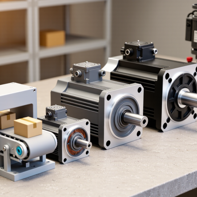
Tip 3: Treat mounting as part of motor selection. Confirm hole spacing, shaft diameter, available clearance, and cable direction before ordering. Check whether the frame can handle vibration and whether the shaft stays aligned under load. A motor that fits on paper may foul a bracket by a few millimeters. One caveat: catalog drawings do not always show every connector or fastener. Measure the actual assembly space and compare it with the drawing.

7 Tips for Choosing the Right DC DC Motor - Compare Efficiency, Gear Ratio, and Mounting with System Requirements

Use this comparison to match motor characteristics to the load, power supply, operating conditions, and available installation space.

Tip What to Compare Example Data or Check How It Affects the System
1. Define the load and duty cycle Required torque, speed, acceleration, and operating time Example requirement: 0.20 N·m at 120 rpm continuously, with occasional starts under load Choose a motor for continuous operation at the required load, not just its short-duration peak rating. Starting and stall conditions can draw substantially more current than normal running.
2. Check voltage and current limits Supply voltage, running current, startup current, and driver capability A motor rated for 12 V should be paired with a supply and driver that can handle its measured operating current and higher startup demand. Voltage affects achievable speed, while load affects current. Confirm the motor, wiring, power supply, and controller are compatible across the full operating range.
3. Compare efficiency at the working point Motor efficiency at the required speed and torque, not only peak efficiency Small brushed DC motors commonly achieve roughly 70–85% efficiency near suitable operating points; brushless DC motors may reach roughly 85–92%. Actual results vary by design and load. Higher efficiency can reduce heat and battery use, but compare performance curves at the intended operating point. Gearbox, controller, and power-conversion losses also affect system efficiency.
4. Select a suitable gear ratio Output speed, output torque, gearbox efficiency, and backlash With a 10:1 reduction, an idealized 1,200 rpm motor produces about 120 rpm at the gearbox output. Actual output torque is lower than the ideal ratio multiplication because of losses. A higher reduction generally lowers speed and increases available output torque. Check the gearbox’s rated torque, efficiency, backlash, and permissible input speed.
5. Verify shaft and mounting fit Mounting pattern, shaft diameter and length, orientation, and clearance Measure the available envelope and confirm the motor’s hole spacing, pilot diameter, shaft dimensions, and connector position against the mechanical drawing. A motor that meets the electrical specification may still require an adapter or redesign if its mounting face, shaft, or cable routing does not fit the assembly.
6. Account for heat and environment Temperature rise, ambient temperature, ventilation, dust, moisture, and vibration Compare the motor’s rated operating temperature and protection rating with the enclosure and expected ambient conditions; allow for heat generated during continuous use. Restricted airflow and high ambient temperature can reduce allowable continuous output. Select suitable protection and thermal margin for the installation environment.
7. Match control and feedback needs Speed control, position accuracy, braking, and feedback signals A basic brushed motor can be speed-controlled with a compatible PWM driver. An encoder can provide speed or position feedback; a brushless motor requires a compatible electronic controller. Choose the control method based on accuracy and response requirements. Check encoder resolution, controller current rating, and any braking or reversing requirements.